Overview
Now we know that Arduino is an open source platform, this means that all the information regarding the hardware and software provided is freely available and can be used by anyone. And it also means that the learning is possible for us now… possible even if we have no basic in electronics or hardcore engineering knowledge. What we need now is a dedication to learn it.
Let’s focus on our main topic here, getting started with Arduino. Imagine if you already have any Arduino board, be it Arduino Uno, or Nano, or Duemilanove, or maybe Mega 2560, the first thing you should do is study the hardware.
So, before we go deep into our discussion here, let us go through the outline of this article, what we aim to understand by the end of this article:
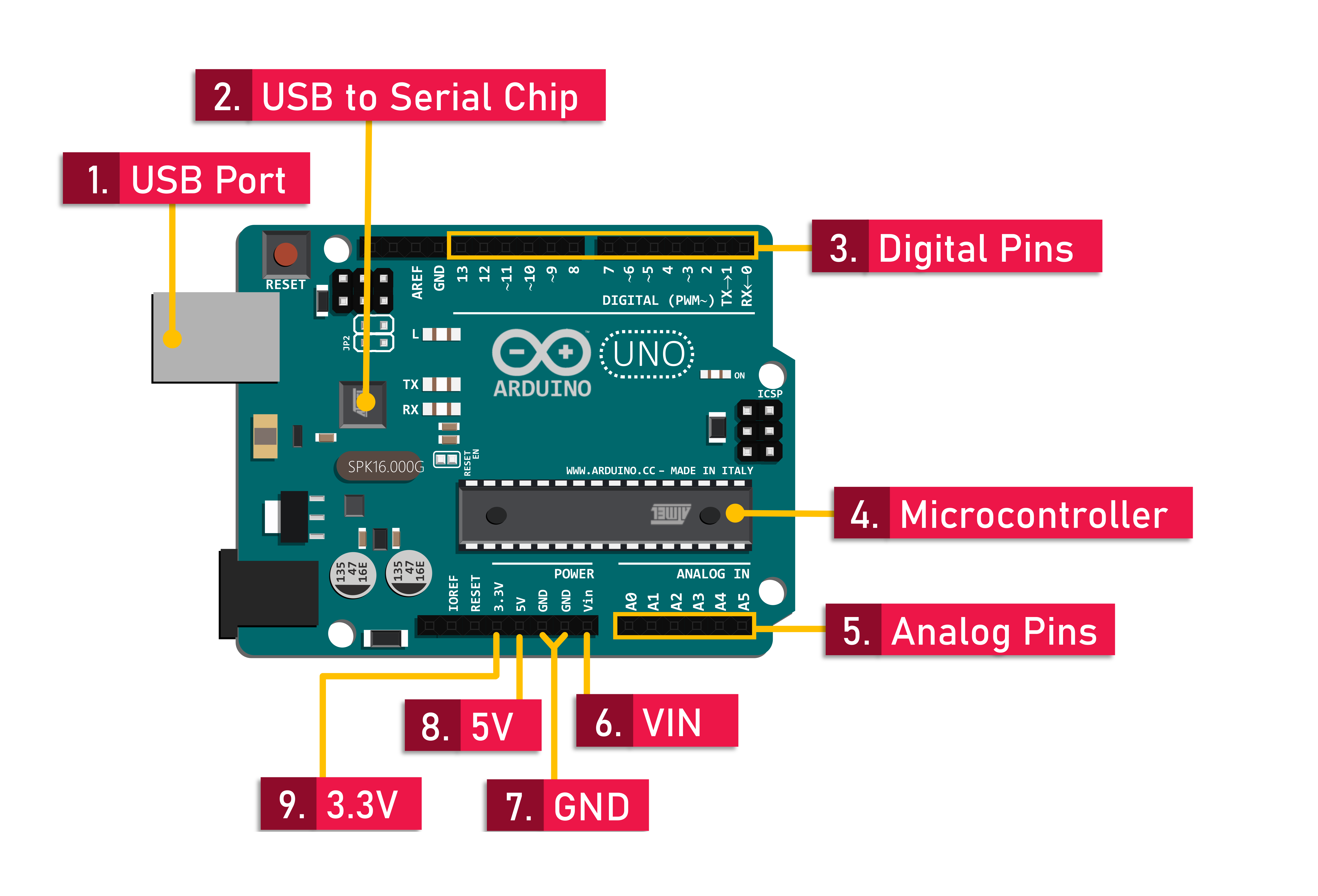
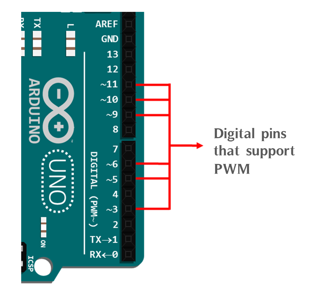
- Exploring The Basic Anatomy of An Arduino Board
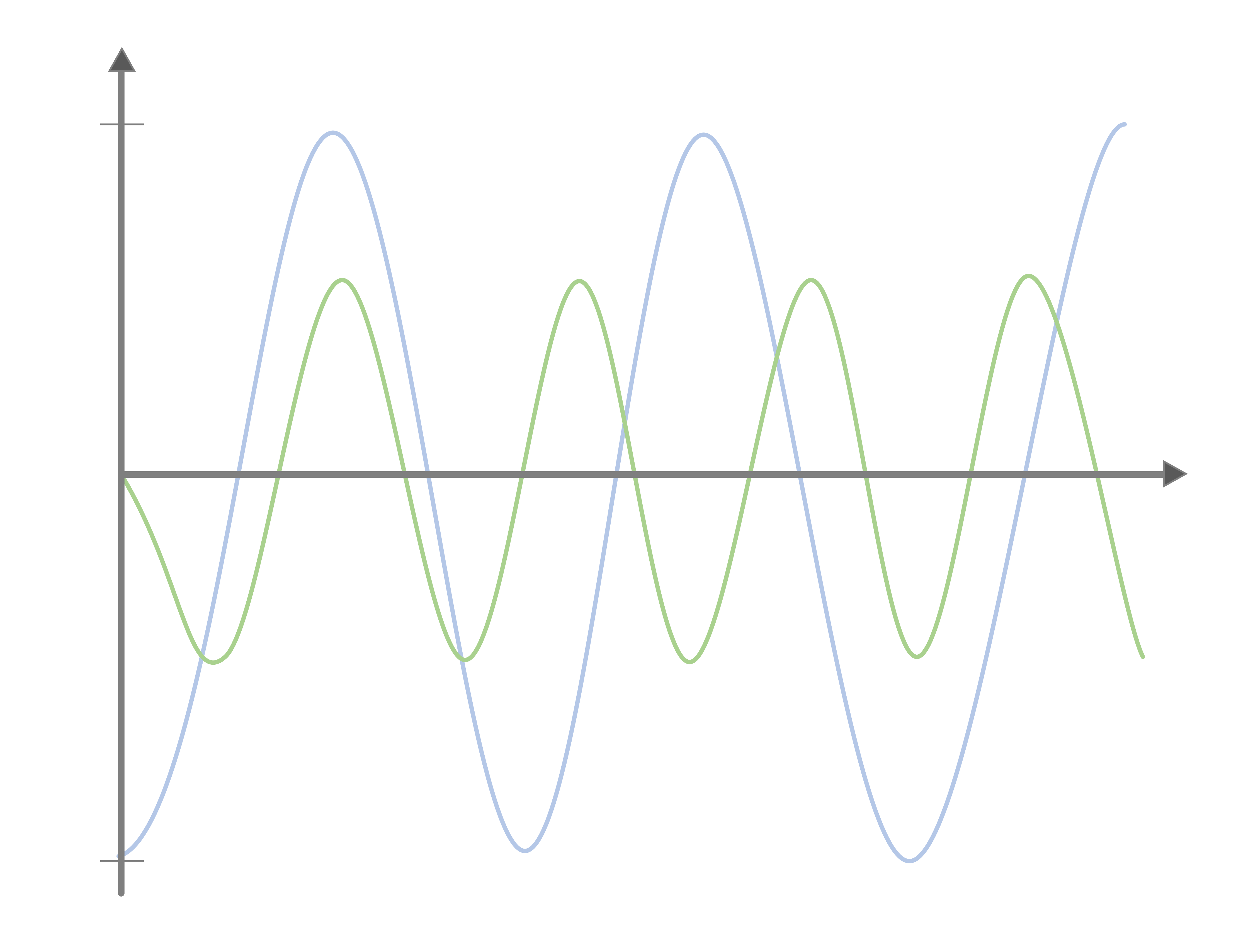
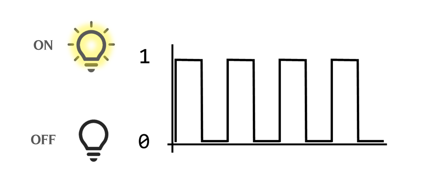
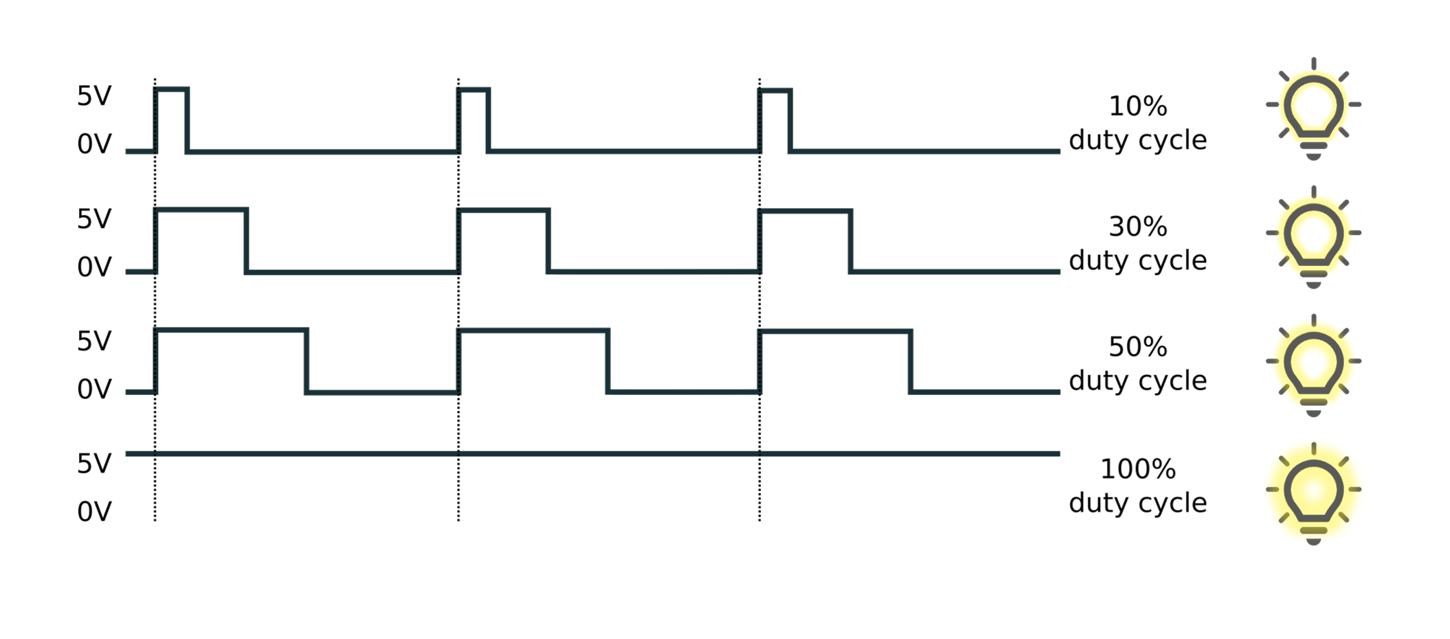
- The Electronic Signals
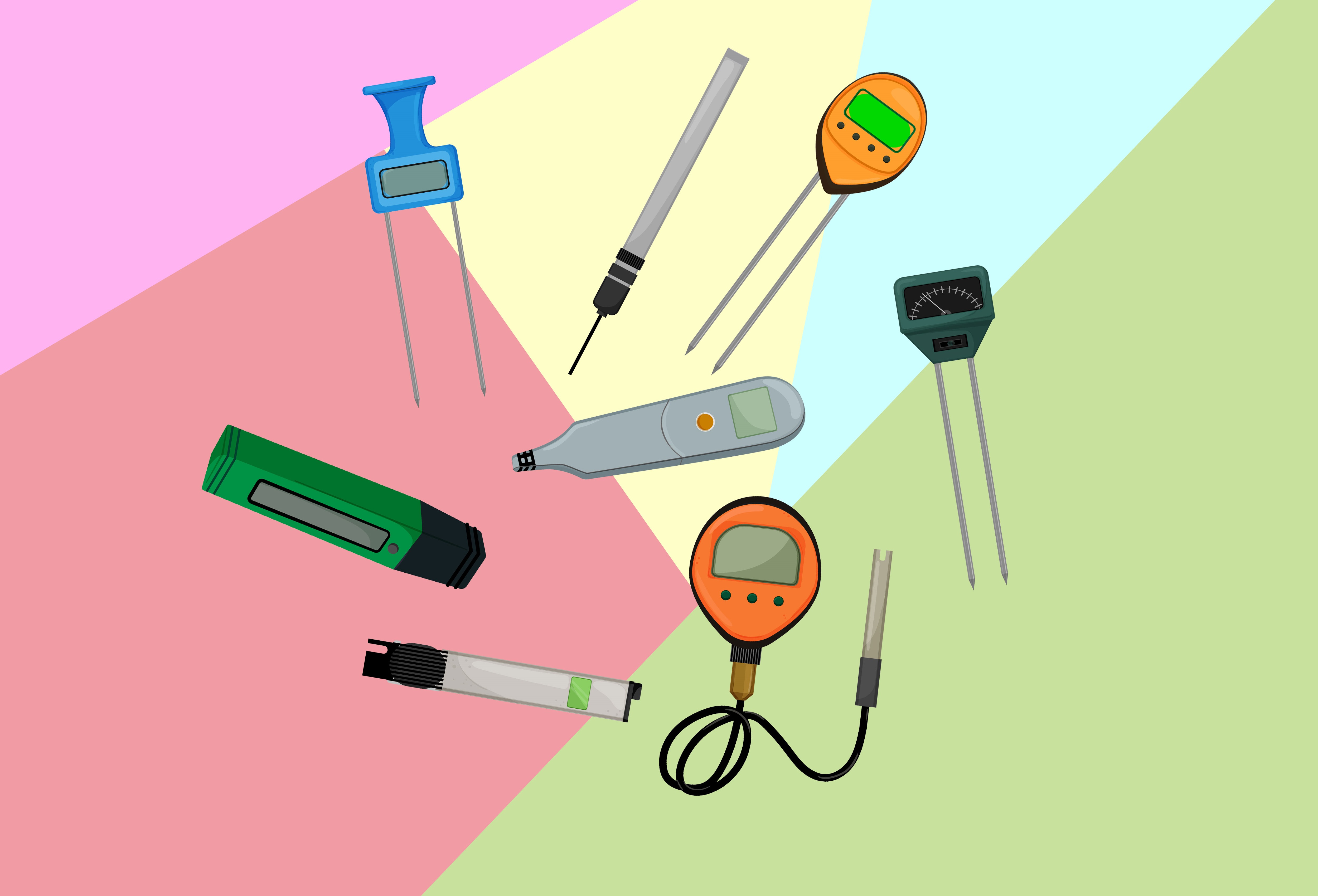
- Sensors and Actuators